Scratchpad OS
Scratchpad OS is simple OS written in modern C++.
Every single step from building cross compiler to documentation is automated, only prerequisites are virtualbox and vagrant.
git clone git@github.com:frainfreeze/scratchpad.git
cd scratchpad && vagrant up
The bootstrap.sh script will get executed on machines boot and install all the tools you need to compile the OS. It will also run makefiles and output OS image in /home/build.
Note
To log into virtual machine run vagrant ssh, to exit the VM run logout, to shutdown the machine run vagrant halt, and finally to terminate use of resources on your machine (including virtual machines disks) run vagrant destroy.
Developing OS is complex task that requires very specific development environment and set of tools. Theoretically one could write an OS in any language he wants, however assembly, C and C++ are de facto languages for this kind of job.
Our compiler suite of choice is GCC, build system cmake, and scripting language Bash.
Everything is build and assembled inside virtual machine built by vagrant. Vagrant
enables us to automate complete complex process of building cross compiler, OS, linking
and producing iso (even building documentation) into a single vagrant up command.
All development and examples were ran on Debian 9. Feel free to work from vagrant machine if you don’t want to bother with setting up everything on your own host OS.
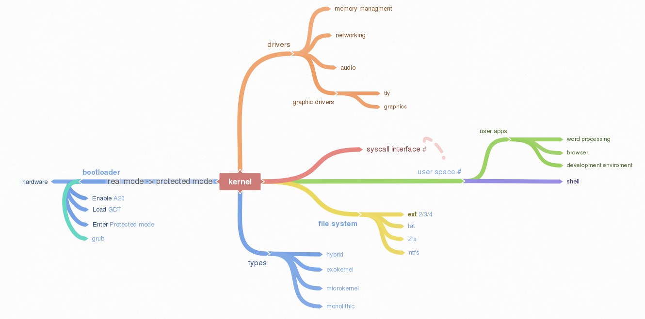
Operating system basics
The job of an operating system is to share a computer among multiple programs and to provide a more useful set of services than the hardware alone supports. The operating system manages and abstracts the low-level hardware, so that, for example, a word processor need not concern itself with which type of disk hardware is being used. It also shares the hardware among multiple programs so that they run (or appear to run) at the same time. Finally, operating systems provide controlled ways for programs to interact, so that they can share data or work together.
x86 is a family of backward-compatible instruction set architectures based on the Intel 8086 CPU and its Intel 8088 variant. The 8086 was introduced in 1978 as a fully 16-bit extension of Intel’s 8-bit-based 8080 microprocessor, with memory segmentation as a solution for addressing more memory than can be covered by a plain 16-bit address. The term “x86” came into being because the names of several successors to Intel’s 8086 processor end in “86”, including the 80186, 80286, 80386 and 80486 processors. [1]
Booting
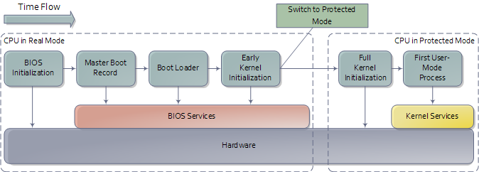
When you turn on a computer, it loads the BIOS from some special flash memory. The BIOS runs self test and initialization routines of the hardware, then it looks for bootable devices. If it finds one, the control is transferred to its bootloader, which is a small portion of executable code stored at the device’s beginning. The bootloader has to determine the location of the kernel image on the device and load it into memory. It also needs to switch the CPU to the so-called protected mode because x86 CPUs start in the very limited real mode by default (to be backwards compatible).
We won’t write a bootloader because that would be a complex project on its own. Fortunately there is a bootloader standard: the Multiboot Specification. Our kernel just needs to indicate that it supports Multiboot and every Multiboot-compliant bootloader can boot it. We will use the Multiboot 2 specification together with the well-known GRUB 2 bootloader.
To indicate our Multiboot 2 support to the bootloader, our kernel must start with a Multiboot Header, which has the following format:
| Field | Type | Value |
|---|---|---|
| magic number | u32 | 0xE85250D6 |
| architecture | u32 | 0 for i386, 4 for MIPS |
| header length | u32 | total header size, including tags |
| checksum | u32 | -(magic + architecture + header_length) |
| tags | variable | |
| end tag | (u16, u16, u32) | (0, 0, 8) |
We can define the constants and header in assembly:
# multiboot header constants
.set ALIGN,    1<<0             # align loaded modules on page boundaries
.set MEMINFO,  1<<1             # provide memory map
.set FLAGS,    ALIGN | MEMINFO  # this is the Multiboot 'flag' field
.set MAGIC,    0x1BADB002       # 'magic number' lets bootloader find the header
.set CHECKSUM, -(MAGIC + FLAGS) # checksum of above, to prove we are multiboot

# Declare a header as in the Multiboot Standard.
.section .multiboot
.align 4
.long MAGIC
.long FLAGS
.long CHECKSUM
We put header into special section so we can force it to be in the start of the final program. The bootloader will search for this magic sequence and recognize us as a multiboot kernel.
Grub moves kernel into protected mode that allows system software to use features such as virtual memory, paging and safe multi-tasking designed to increase an operating system’s control over application software.
Device drivers
A device driver is a specific type of computer software developed to allow interaction with hardware devices. Typically this constitutes an interface for communicating with the device, through the specific computer bus or communications subsystem that the hardware is connected to, providing commands to and/or receiving data from the device, and on the other end, the requisite interfaces to the operating system and software applications. It is a specialized hardware-dependent computer program which is also operating system specific that enables another program, typically an operating system or applications software package or computer program running under the operating system kernel, to interact transparently with a hardware device, and usually provides the requisite interrupt handling necessary for any necessary asynchronous time-dependent hardware interfacing needs.
The screen
Our kernel gets booted by GRUB in text mode. That is, it has available to it a framebuffer (area of memory) that controls a screen of characters (not pixels) 80 wide by 25 high. The area of memory known as the framebuffer is accessible just like normal RAM, at address 0xB8000. It is important to note, however, that it is not actually normal RAM. It is part of the VGA controller’s dedicated video memory that has been memory-mapped via hardware into our linear address space. The framebuffer is just an array of 16-bit words, each 16-bit value representing the display of one character. Highest 8 bits are ASCII value of the character, bits 7-4 represent the background and bits 3-0 foreground color.
Bit:     |15 14 13 12 11 10 9 8|7 6 5 4|3 2 1 0|
Content: | ASCII               | FG    | BG    |
The offset from the start of the framebuffer of the word that specifies a character at position x, y
is simply (y * 80 + x) * 2.
Say we want to write ‘A’(65,or 0x41) with green foreground and dark grey background(8) at place (0,0)
we would write assembly code mov [0x000B8000], 0x4128 where 0x41 represents ASCII A, 2 is green
and 8 is dark grey color. Second cell (0,1) would be 0x000B8000 + 16 = 0x000B8010.
Reference table of available colors:
Color Value Color Value Color Value Color Value Black 0 Red 4 Dark grey 8 Light red 12 Blue 1 Magenta 5 Light blue 9 Light magenta 13 Green 2 Brown 6 Light green 10 Light brown 14 Cyan 3 Light grey 7 Light cyan 11 White 15
The VGA controller also has some ports on the main I/O bus, which we can use to send it specific instructions. (Among others) it has a control register at 0x3D4 and a data register at 0x3D5. We will use these to instruct the controller to update it’s cursor position.
GDT
The Global Descriptor Table (GDT) is a data structure used by Intel x86-family processors starting with the 80286 in order to define the characteristics of the various memory areas used during program execution, including the base address, the size, and access privileges like executability and writability. These memory areas are called segments in Intel terminology.
The GDT can hold things other than segment descriptors as well. Every 8-byte entry in the GDT is a descriptor, but these can also be Task State Segment (TSS) descriptors, Local Descriptor Table (LDT) descriptors, or Call Gate descriptors.
The x86 architecture has two methods of memory protection and of providing virtual memory - segmentation and paging.
With segmentation, every memory access is evaluated with respect to a segment. That is, the memory address is added to the segment’s base address, and checked against the segment’s length. With paging, the address space is split into (usually 4KB, but this can change) blocks, called pages. Each page can be mapped into physical memory - mapped onto what is called a ‘frame’. Or, it can be unmapped. This way one can create virtual memory spaces.
Both of these methods have their advantages, but paging is much better. Segmentation is, although still usable, fast becoming obsolete as a method of memory protection and virtual memory. In fact, the x86-64 architecture requires a flat memory model (one segment with a base of 0 and a limit of 0xFFFFFFFF) for some of it’s instructions to operate properly.
Segmentation is, however, completely in-built into the x86 architecture. Every memory access which a program can perform always goes through a segment. It’s impossible to get around it, therefore we need to setup Global Descriptor Table - a list of segment descriptors.
While GRUB does setup GDT for us we don’t know where it is nor what is in it. In the x86, there are 6 segmentation registers. Each holds an offset into the GDT. They are cs (code segment), ds (data segment), es (extra segment), fs, gs, ss (stack segment). The code segment must reference a descriptor which is set as a ‘code segment’. There is a flag for this in the access byte. The rest should all reference a descriptor which is set as a ‘data segment’.
To set up GDT we need to create GDT entry structure and a special pointer structure which we give to the processor so it can find the GDT.
Interrupts
In system programming, an interrupt is a signal to the processor emitted by hardware or software indicating an event that needs immediate attention. An interrupt alerts the processor to a high-priority condition requiring the interruption of the current code the processor is executing. The processor responds by suspending its current activities, saving its state, and executing a function called an interrupt handler (or an interrupt service routine, ISR) to deal with the event. This interruption is temporary, and, after the interrupt handler finishes, the processor resumes normal activities.
There are 2 types of interrupts plus Exceptions:
- Hardware interrupts: are sent to the processor from an external device (keyboard, mouse, hard disk, ...). Hardware interrupts were introduced as a way to reduce wasting the processor’s valuable time in polling loops, waiting for external events.
- Software interrupts: are initiated voluntarily by the software. It’s used to manage system calls.
- Exceptions are used for errors or events occurring during program execution that are exceptional enough that they cannot be handled within the program itself (division by zero, page fault, ...)
The PIC (Programmable interrupt controller)is a device that is used to combine several sources of interrupt onto one or more CPU lines, while allowing priority levels to be assigned to its interrupt outputs. When the device has multiple interrupt outputs to assert, it asserts them in the order of their relative priority.
The Interrupt Descriptor Table tells the processor where to find handlers for each interrupt. It is very similar to the GDT. It is just an array of entries, each one corresponding to an interrupt number. There are 256 possible interrupt numbers, so 256 must be defined. If an interrupt occurs and there is no entry for it (even a NULL entry is fine), the processor will panic and reset. The processor will sometimes needs to signal the kernel. Something major may have happened, such as a divide-by-zero, or a page fault. To do this, it uses the first 32 interrupts. It is therefore doubly important that all of these are mapped and non-NULL - else the CPU will triple-fault and reset.
Like the GDT, the IDT is loaded using the LIDTL assembly instruction. It expects the location of a IDT description structure (pointer).
We define our IDT table and then load it using LIDTL. The IDT table can be stored wherever we want in memory, its address should just be signaled to the process using the IDTR registry. After intialization of our IDT, we can activate interrupts by configuring the PIC.
PS/2 Keyboard
The PS/2 Keyboard is a device that talks to a PS/2 controller using serial communication. Ideally, each different type of PS/2 controller driver should provide some sort of standard/simple “send byte/receive byte” interface, and the PS/2 Keyboard driver would use this interface without caring about lower level details (like what type of PS/2 controller the device is plugged into).
The PS/2 Keyboard accepts commands and sends responses to those commands, and also sends scan codes indicating when a key was pressed or released. A command is one byte. Some commands have data byte/s which must be sent after the command byte. The keyboard typically responds to a command by sending either an “ACK” (to acknowledge the command) or a “Resend” (to say something was wrong with the previous command) back.
Memory management
Virtual memory is an abstraction of physical memory. The purpose of virtual memory is generally to simplify application development and to let processes address more memory than what is actually physically present in the machine. We also don’t want applications messing with the kernel or other applications’ memory due to security.
In the x86 architecture, virtual memory can be accomplished in two ways: segmentation and paging. Paging is by far the most common and versatile technique, and we’ll implement it the next chapter. Some use of segmentation is still necessary to allow for code to execute under different privilege levels.
Segmentation
Segmentation in x86 means accessing the memory through segments. Segments are portions of the address space, possibly overlapping, specified by a base address and a limit. To address a byte in segmented memory you use a 48-bit logical address: 16 bits that specifies the segment and 32-bits that specifies what offset within that segment you want. The offset is added to the base address of the segment, and the resulting linear address is checked against the segment’s limit. If everything works out fine the result is a linear address. When paging is disabled, then the linear address space is mapped 1:1 onto the physical address space, and the physical memory can be accessed. We enable segmentation via GDT.
Paging
Segmentation translates a logical address into a linear address. Paging translates these linear addresses onto the physical address space, and determines access rights and how the memory should be cached.
Paging in x86 consists of a page directory (PDT) that can contain references to 1024 page tables (PT), each of which can point to 1024 sections of physical memory called page frames (PF). Each page frame is 4096 byte large. In a virtual (linear) address, the highest 10 bits specifies the offset of a page directory entry (PDE) in the current PDT, the next 10 bits the offset of a page table entry (PTE) within the page table pointed to by that PDE. The lowest 12 bits in the address is the offset within the page frame to be addressed.
All page directories, page tables and page frames need to be aligned on 4096 byte addresses. This makes it possible to address a PDT, PT or PF with just the highest 20 bits of a 32 bit address, since the lowest 12 need to be zero.
The PDE and PTE structure is very similar to each other: 32 bits (4 bytes), where the highest 20 bits points to a PTE or PF, and the lowest 12 bits control access rights and other configurations. 4 bytes times 1024 equals 4096 bytes, so a page directory and page table both fit in a page frame themselves.
The simplest kind of paging is when we map each virtual address onto the same physical address, called identity paging. This can be done at compile time by creating a page directory where each entry points to its corresponding 4 MB frame.
Page Frame Allocation
Role of page frame allocator is simply to tell the OS which parts of memory are free to use. We need to know how much memory is available on the computer the OS is running on. We can read it from the multiboot structure passed to us by GRUB. GRUB collects the information we need about the memory - what is reserved, I/O mapped, read-only etc.
Processes
Creating new processes is usually done with two different system calls: fork and exec. fork creates an exact copy of the currently running process, while exec replaces the current process with one that is specified by a path to the location of a program in the file system.
System calls
System calls is the way user-mode applications interact with the kernel - to ask for resources, request operations to be performed, etc.
System calls are traditionally invoked with software interrupts. The user applications put the appropriate values in registers or on the stack and then initiates a pre-defined interrupt which transfers execution to the kernel.
When system calls are executed, the current privilege level is typically changed from PL3 to PL0 (if the application is running in user mode). To allow this, the DPL of the entry in the IDT for the system call interrupt needs to allow PL3 access.
To enable system calls we need to setup a TSS before entering user mode.
File system
The purpose of file system is to organise and store data. File system typically supports sharing data among users and applications, as well as persistence so data is still available after reboot.
The communication between computer and optical drive can be done by various types of controllers and cabling such as ATAPI, SATA, or USB. Many operating systems offer some kind of generic SCSI driver interface which abtracts the various transports to a single transaction API. These APIs are also available in userspace.
Scratchpad OS implements ISO 9660 file system and ATA/ATAPI drivers.
PCI IDE Controller
DE is a keyword which refers to the electrical specification of the cables which connect ATA drives (like hard drives) to another device. The drives use the ATA (Advanced Technology Attachment) interface. An IDE cable also can terminate at an IDE card connected to PCI.
Parallel ATA (PATA), originally AT Attachment, is an interface standard for the connection of storage devices such as hard disk drives, floppy disk drives, and optical disc drives in computers. It uses the underlying AT Attachment (ATA) and AT Attachment Packet Interface (ATAPI) standards.
ATAPI is an extension to ATA (recently renamed to PATA) and Serial ATA, which adds support for the SCSI command set. With ATAPI a greater variety of devices can be connected to a computer than with ATA alone.
ATAPI devices are also “speaking ATA” because the ATA physical interface and protocol are still being used to send the packets. On the other hand, ATA hard drives and solid state drives do not use ATAPI. ATAPI is basically a way to issue SCSI commands to a CD-ROM, CD-RW, DVD, or tape drive, attached to the ATA bus.
ATAPI uses a very small number of ATA commands. The most important are the PACKET command (0xA0), and IDENTIFY PACKET DEVICE (0xA1).
An IDE driver does not need to know whether a drive is parallel or serial, it only has to know whether it’s using ATA or ATAPI. IDE can connect up to 4 drives. Each drive can be one of the following:
- ATA (Serial): Used for most modern hard drives.
- ATA (Parallel): Commonly used for hard drives.
- ATAPI (Serial): Used for most modern optical drives.
- ATAPI (Parallel): Commonly used for optical drives.
ISO 9660
ISO 9660 is the standard file system for CD-ROMs. It is also widely used on DVD and BD media and may as well be present on USB sticks or hard disks. Its specifications are available for free under the name ECMA-119.
An ISO 9660 sector is normally 2 KiB long. Although the specification allows for alternative sector sizes, you will rarely find anything other than 2 KiB. ISO 9660 file systems can have up to 2 exp 32 blocks, i.e. 8 TiB.
The following is the rough overall structure of the ISO 9660 file system:
| ISO 9660 File System | |
|---|---|
| System Area | Unused by ISO 9660 |
| Data Area | Volume Descriptor Set Path tables, Directories and Files |
The ISO 9660 standard specifies three ways to encode 16 and 32-bit integers, using either little-endian (least-significant byte first), big-endian (most-significant byte first), or a combination of both (little-endian followed by big-endian). Both-endian (LSB-MSB) fields are therefore twice as wide. For this reason, 32-bit LBA’s often appear as 8 byte fields. Where a both-endian format is present, the x86 architecture makes use of the first little-endian sequence and ignores the big-endian sequence.
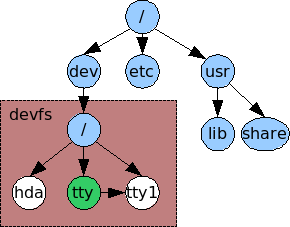
The virtual filesystem
A VFS is intended to abstract away details of the filesystem and location that files are stored, and to give access to them in a uniform manner. They are usually implemented as a graph of nodes; Each node representing either a file, directory, symbolic link, device, socket or pipe. Each node should know what filesystem it belongs to and have enough information such that the relevant open/close/etc functions in its driver can be found and executed. A common way to accomplish this is to have the node store function pointers which can be called by the kernel. We need a few function pointers:
- Open - Called when a node is opened as a file descriptor.
- Close - Called when the node is closed.
- Read & Write
- Readdir
- Finddir
Mountpoints are the UNIX way of accessing different file systems. A filesystem is mounted on a directory - any subsequent access to that directory will actually access the root directory of the new filesystem. So essentially the directory is told that it is a mountpoint and given a pointer to the root node of the new filesystem.
References
Books:
- xv6 book 10th ed, R. Cox, F. Kaashoek, R. Morris
- The little book about OS development, E. Helin, A. Renberg
- Operating systems: from 0 to 1, T.D. Hoang
- Writing a Simple Operating System, N. Blundell
- Operating System Concepts 10th ed., A. Silberschatz, G. Gagne, P.B. Galvin
- Operating systems design and implementation 3rd ed, A. Tanenbaum
- The Design of the UNIX Operating System, M.J. Bach
- The Design and Implementation of the FreeBSD Operating System
- Intel® 64 and IA-32 Architectures Software Developer’s Manual (Vol 3)
Internet pages:
- https://en.wikipedia.org/wiki/X86
- https://www.gnu.org/software/grub/manual/legacy
- https://linux.die.net/man/1/qemu-img
- https://wiki.osdev.org/C%2B%2B
- https://wiki.osdev.org/Boot_Sequence
- https://manybutfinite.com/post/how-computers-boot-up
- https://wiki.osdev.org/GCC_Cross-Compiler
- https://en.wikipedia.org/wiki/Booting#BOOT-LOADER
- https://en.wikipedia.org/wiki/GNU_GRUB
- http://www.brokenthorn.com
- https://en.wikipedia.org/wiki/Interrupt
- https://en.wikipedia.org/wiki/File_system
- https://en.wikipedia.org/wiki/Parallel_ATA
- https://wiki.osdev.org/ATAPI
- https://wiki.osdev.org/PCI_IDE_Controller
Development environment
Since we will be building and installing a lot of tools frequently many things could go wrong. To make our life easier we can use virtual machines, and to make everything even more hassle free, we can utilize virtual machine manager, such as vagrant.
Preparing the box
Installing virtualbox and vagrant on Debian 9 is rather straightforward:
# add stretch-backports main and contrib to your apt sources
sudo apt install virtualbox
wget https://releases.hashicorp.com/vagrant/2.1.1/vagrant_2.1.1_x86_64.deb
sudo dpkg -i vagrant_2.1.1_x86_64.deb
Once we have the software we can write small vagrant script:
# -*- mode: ruby -*-
# vi: set ft=ruby :
Vagrant.configure("2") do |config|
  config.vm.box = "generic/debian9"
  config.vm.box_check_update = false
  config.vm.synced_folder ".", "/home/src"
  config.vm.provision :shell, path: "bootstrap.sh"
end
Save it as Vagrantfile in the root of the project. This particular vagrant file downloads
Debian 9 image, mounts its root directory under /home/src in the virtual machine and
executes bootstrap.sh. Shell script then invokes i686-elf-tools.sh script that
downloads necessary sources and compiles cross compiler. Once the compiler is built
bootstrap script invokes cmake that builds the OS itself, bootable iso and
documentation.
Finally, starting whole building process is as simple as executing vargant up in the
projects root directory.
Cross Compiler
An cross-compiler is a compiler that runs on platform A (the host), but generates executables for platform B (the target). These two platforms may (but do not need to) differ in CPU, operating system, and/or executable format. In our case, the host platform is our current operating system, and the target platform is the operating system we are building.
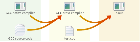
GCC is great open source compiler and we will use it as cross compiler for our OS. The GNU Compiler Collection is an advanced piece of software with many dependencies. We will also need Binutils which are collection of binary tools, since we are also interested in linker and assembler.
Cross compiler building process is rather complex and lengthy process. See i686-elf-tools.sh for details.
First steps
Small assembly code to demonstrate building bootable iso image.
global loader                   ; the entry symbol for ELF

MAGIC_NUMBER equ 0x1BADB002     ; define the magic number constant
FLAGS        equ 0x0            ; multiboot flags
CHECKSUM     equ -MAGIC_NUMBER  ; calculate the checksum
                                ; (magic number + checksum + flags should equal 0)

section .text:                  ; start of the text (code) section
align 4                         ; the code must be 4 byte aligned
    dd MAGIC_NUMBER             ; write the magic number to the machine code,
    dd FLAGS                    ; the flags,
    dd CHECKSUM                 ; and the checksum

loader:                         ; the loader label (defined as entry point in linker script)
    mov eax, 0xCAFEBABE         ; place the number 0xCAFEBABE in the register eax
.loop:
    jmp .loop                   ; loop forever
The file loader.s can be compiled into a 32 bits ELF [18] object file with the following command:
nasm -f elf32 loader.s
The code must now be linked to produce an executable file, which requires some extra thought compared to when linking most programs. We want GRUB to load the kernel at a memory address larger than or equal to 0x00100000 (1 megabyte (MB)), because addresses lower than 1 MB are used by GRUB itself, BIOS and memory-mapped I/O. Therefore, the following linker script is needed (written for GNU LD):
ENTRY(loader)                /* the name of the entry label */

SECTIONS {
    . = 0x00100000;          /* the code should be loaded at 1 MB */

    .text ALIGN (0x1000) :   /* align at 4 KB */
    {
        *(.text)             /* all text sections from all files */
    }

    .rodata ALIGN (0x1000) : /* align at 4 KB */
    {
        *(.rodata*)          /* all read-only data sections from all files */
    }

    .data ALIGN (0x1000) :   /* align at 4 KB */
    {
        *(.data)             /* all data sections from all files */
    }

    .bss ALIGN (0x1000) :    /* align at 4 KB */
    {
        *(COMMON)            /* all COMMON sections from all files */
        *(.bss)              /* all bss sections from all files */
    }
}
Save the linker script into a file called link.ld. The executable can now be linked with the following command:
ld -T link.ld -melf_i386 loader.o -o kernel.elf
If you have GRUB installed, you can check whether a file has a valid Multiboot version 1 header, which is the case for our kernel. It’s important that the Multiboot header is within the first 8 KiB of the actual program file at 4 byte alignment. This can potentially break later if you make a mistake in the boot assembly, the linker script, or anything else that might go wrong. If the header isn’t valid, GRUB will give an error that it can’t find a Multiboot header when you try to boot it. This code fragment will help you diagnose such cases:
grub-file --is-x86-multiboot kernel.elf
Grub-file is quiet but will exit 0 (successfully) if it is a valid multiboot kernel and exit 1
(unsuccessfully) otherwise. You can type echo $? in your shell immediately afterwards to see
the exit status.
Building ISO
We will create the kernel ISO image with the program grub-mkrescue. A folder must first be created that contains the files that will be on the ISO image. The following commands create the folder and copy the files to their correct places:
mkdir -p iso/boot/grub              # create the folder structure
cp kernel.bin iso/boot/             # copy the kernel
A configuration file menu.cfg for GRUB must be created. This file tells GRUB where the kernel is located and configures some options:
set timeout=30
set default=0
menuentry "Scratchpad OS" {
    multiboot /boot/kernel.bin
    boot
}
Place the file in the folder iso/boot/grub/. The contents of the iso folder should now look like the following figure:
iso
└── boot
    ├── grub
    │   └── grub.cfg
    └── kernel.bin
Finally, make a ISO9660 image file by invoking:
grub-mkrescue -o os.iso iso
This produces a file named os.iso, which then can be burned into a CD (or a DVD) or loaded directly into virtual machine. The ISO image contains the kernel executable, the GRUB bootloader and the configuration file.
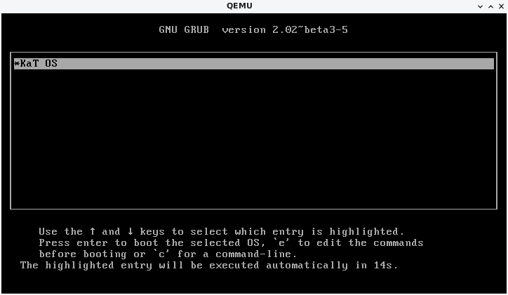
To run the OS in QEMU emulator execute:
qemu-system-i386 -cdrom os.iso
Scratchpad OS Source Code
src
|-bin
|-docs
|-libs
|-kernel
|  |-devices
|  |-filesys
|  |-sys
|-userland
Bin contains built ISO image, docs documentation, libs contains libc and libcpp, userland contains user space aplications.
Kernel directory in its root has main.cpp which is os entry point. Devices contain cpu, display, input and storage drivers. Sys contains memory, process and system drives, including cpp runtime.
Src directory aditionaly contains make file, menu file for grub legacy, stage2_eltorito...
Notes
x86 Assembly
Lets make some test files
> nano test.asm
> nasm -f bin test.asm -o test  (apt-get nasm)
   -f specifies the file format of the output file(-o)
   in this case its bin(flat binary output without any extra information,
   as in assembly code -> machine code(as is, without overhead of metadata)

    Note: using bin format puts nasm by default into 16-bit mode, to enable 32bit
      add "bits 32" at beginning of an nasm source file

we can examine the output using hd(HexDump)
> hd test
00000000 66 ff e0            |f..|
00000003
We can see that file only consists of 3 bytes : 66 ff e0, which is equivalent
to the instruction jmp eax


In next few examples im using 'a' as (labeled memory address)/(register)
mov a,0x1    ;Move hex '1' to 'a'
mov a,[0x1]  ;Move value on location '0x1' to 'a'
| calc |
add a   ;a=a+0x1 | (a=a+1)
add a,b ;a=a+b

sub a,b ;a=a-b

;To multiply we need to use eax
mov eax,5  ; eax = 5 (eax is acc used by multiplication)
imul eax,2 ; eax = eax*2
;imul Performs singed multiply, we can also use mul to perform unsigned mult.

; Divsion
mov eax, 5       ;eax = 5
cdq              ;?
idiv 2           ;Perform division,store result in 'eax' and store reminder in 'edx'
mov result,eax   ;result = edx  -> result==2
mov reminder,edx ;reminder=edx -> reminder == 1

So basicly from Division we can get '/' and '%' as result
| Logic |
; NEG
mov a,5
neg a ;a = 0-a , that means a= -a , in this case a==-5

; AND (performes '&', not '&&')
;That means if we have 0101 and 0001 ,result would be 0001
;Few more examples: 1111 & 1000 == 1000,1111 & 1101 == 1101
and eax,a

; OR
; Similar to and , it performs bitwise OR
; 1100 | 0000 == 1100,1010 | 0101 == 1111
or eax,a

; XOR
; if 2 bits are diferend resulting bit is 1
; 1010 xor 1001 == 0011, 1111 xor 1101 == 1101
xor eax,a
| Bit shifting |
; LEFT (sal,shl -google diferences)
mov eax,5   ;eax = 5 (eax = 0101***)
; ***Of course if it was 16,32,64 bit it would have more 0
shl eax,0x8 ;eax << 8 , shift eax 8 bits to left

; RIGHT (sar,shl -google diferences)
mov eax,5
shr eax,0x8 ;eax >> 8, shift eax 8 bits to right
| stack |
> push -> add new element on top of the stack
> pop -> remove the top-most element from the stack

x86 uses 'esp' register to point to the top of the stack(the newest element)
GNU Debugger
- make some test C file(simple hello world)
gdb hello.c(gdb) info target, Entry point - First code the program runs, example: “Entry point: 0x580”
- same like “info target” but with more info
- (gdb)
maint info sections
- you can also display only few sections
- (gdb)
maint info sections .text .data .bss
- displat only sections that contain “CODE”
- (gdb)
maint info sections CODE
- list all function names and their loaded addresses you can use regex to filter also
- (gdb)
info functions
- list all global and static variable names you can use regex also
- (gdb)
info variables
- List current values in commonly used registers
- (gdb)
info registers
- display assembly code of a function
- (gdb)
disassemble main
- display assembly code with source code
- (gdb)
disassemble /s main
- display assembly code with souece code and hex
- (gdb)
disassemble /rs main
- display function in a specific file
- (gdb)
disassemble /rs 'hello.c'::main
- start running the program
- (gdb)
r
- instead of running from start to finish run until line 3
- (gdb)
b 3
- Proceed to the next statement,first line is output produced after executing that line, 2nd line shows where gdb stops currently
- (gdb)
n